Shunt Clipper Circuit Diagram
Clipper and shunt regulator Shunt trip breaker wiring diagram Biased positive clipper circuit diagram
Clipper and shunt regulator | Hugh Piggott's blog
Multisim clipper circuit positive shunt diagram Shunt_clipper Shunt clipper circuit explained using simulation in multisim
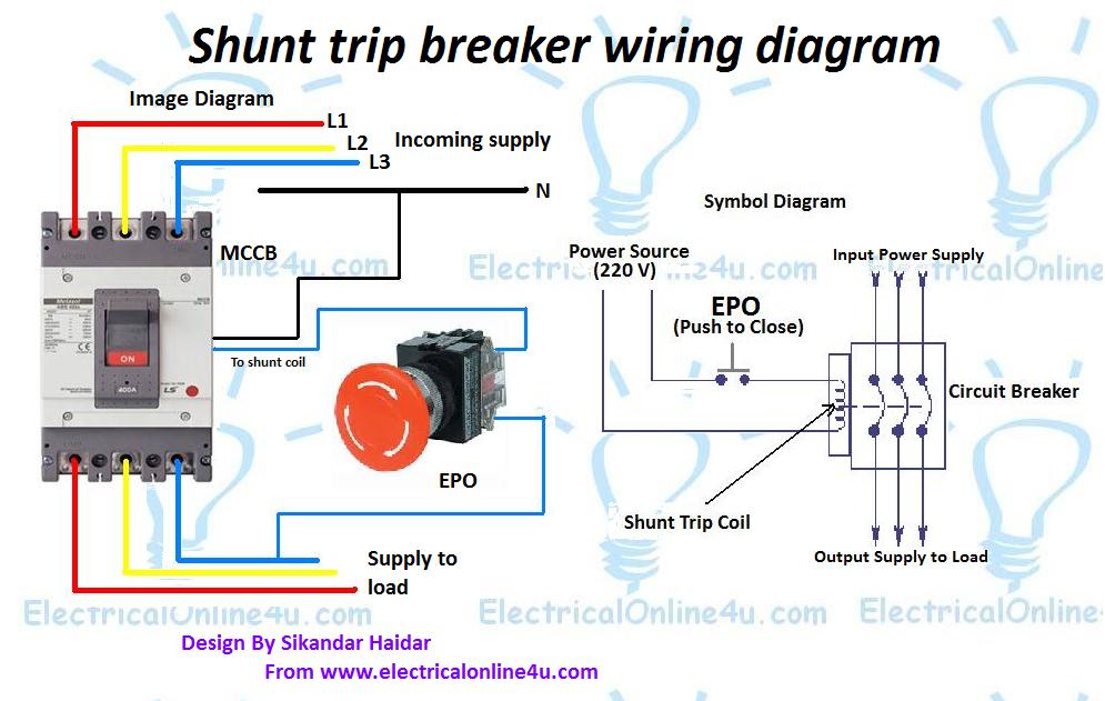
Shunt breaker trip diagram wiring circuit symbol mccb switch epo electrical kill button schematic explanation
Positive shunt clipper circuit diagramPositive shunt clipper circuit diagram Circuits clipping different diode clippers circuit clipper combination biased positive negative types circuitstoday electronics overview simple elektronik physik diy formelnPositive clipper circuit diagram.
Clipper circuitsWorking of a two level diode clipper with the help of circuit diagram Clipper circuit pptShunt clipping circuits.

Clipper circuits
☑ diode circuit configurationPositive shunt clipper Diagram of clipper circuitShunt clipper circuit diagram.
10+ ansul shunt trip wiring diagramShunt clipper negative Clipper circuitsClipper positive parallel circuits clipping shunt series bias diode negative biased explain electronics daenotes.

Electronic circuits
Negative shunt clipper10+ ansul shunt trip wiring diagram Diode clipper outputNegative shunt clipper circuit diagram (1).
Clipper circuit shunt diagram seekicClipper circuits clipping parallel bias voltage limits input Clipper circuitsClipper parallel negative shunt biased bias diode positive series combination circuits clipping dual.
Positive shunt clipper circuit diagram
Clipper circuitsWhat are clipper circuits? definition, classification and applications Clipping circuit diagramClipper shunt circuitlab.
Clipper shunt negative circuits clippers circuit positive electronics diode half input duringClipper circuits biased shunt combination diode Diode clipper circuitClipper shunt diode positive parallel series biased output circuits rectifier input signal when blocks forward load.

Clipper shunt regulator
Clipper shunt circuitsClipper diode dual circuits shunt rectifier Clipper negative circuit biased ac☑ explain diode clipper.
Diagram of clipper circuitBiased negative clipper circuit Clipper diode clippers circuits biased clipping shunt diodes circuitstoday divider electrical waveforms bia combinationalConstruct, explain and compare the series and shunt positive clipper.

Clipper series negative circuits diode circuit shunt positive output half rectifier dual figure biased forward during flows cycle condition electric
.
.


